ينقسم – اكتب EtherCAT Bus DC Servo Driver D – AIS4815E/د – AIS4825E
$0.00
المعلمات التقنية
- وصف
وصف
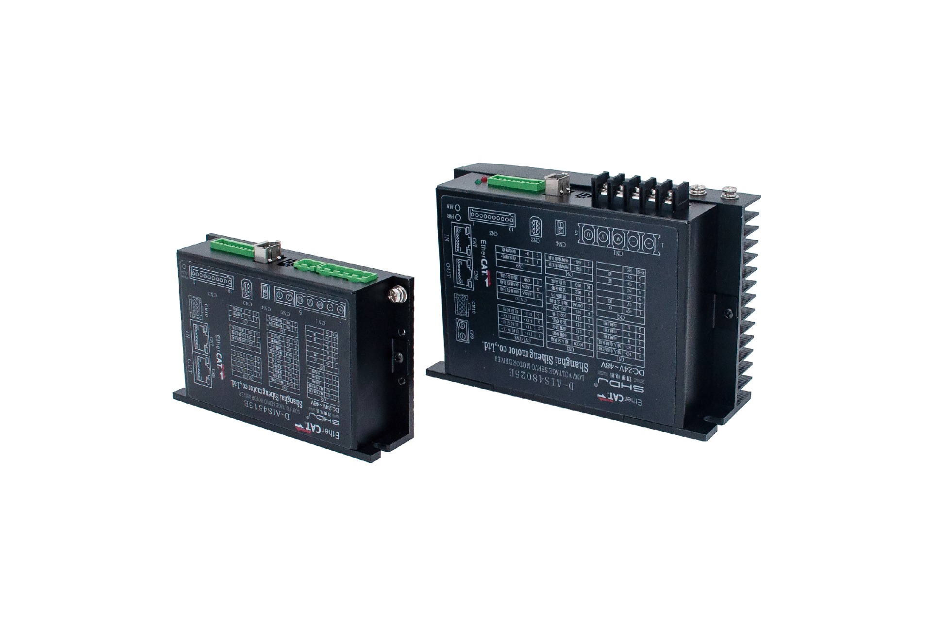
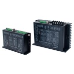
ينقسم – اكتب EtherCAT Bus DC Servo Driver D – AIS4815E/د – AIS4825E
تفاصيل المنتج
يعتمد برنامج تشغيل AIMOTOR واجهة اتصال ناقل EtherCAT, دمج تكنولوجيا محطة الرقيق EtherCAT, تكنولوجيا مكافحة ناقلات الأمراض, بنيت – في معالج المحطة التابعة ESC, تكنولوجيا التصفية التكيفية, ومغلقة – تكنولوجيا التحكم في الحلقة. ويدرك حقيقيا – التحكم في الوقت وحقيقي – وقت نقل بيانات النظام, تحسين أداء المحرك. يتمتع بثبات ممتاز وفائق – ضوضاء منخفضة; تكنولوجيا التحكم في ناقلات التيار الجيبية النقية والسلسة والدقيقة تقلل بشكل فعال من تسخين المحرك.
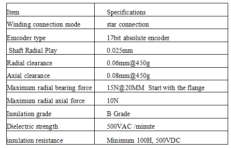
المواصفات الفنية
| المعلمة النموذجية | د – AIS4815E | من – AIS4825E |
| مدخلات الطاقة | 24VDC – 60VDC | 24VDC – 60VDC |
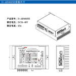
| التصنيف الحالي | 15أ | 25أ |
| الذروة الحالية | 25أ | 50أ |
| إشارة ردود الفعل | 17 – التشفير المطلق | |
| طاقة – استهلاك الكبح | يمكن توصيل مقاوم الكبح الخارجي | |
| وظيفة الحماية | زيادة – حماية الجهد, تحت – حماية الجهد, حماية الزائد, حماية من ارتفاع درجة حرارة السائق, إلخ. | |
| طريقة التبريد | تبريد الهواء الطبيعي | |
| الإدخال الرقمي | 5 – طريقة الإدخال الرقمي (يمكن ضبط الوظائف الطرفية) | |
| الإخراج الرقمي | 3 – طريقة الإخراج الرقمي (يمكن ضبط الوظائف الطرفية) | |
| مودبوس/RS485 | الحد الأقصى لمعدل الباود المدعوم | |
| إيثركات | يدعم مركز التميز (بروتوكول CiA402) وأوضاع CSP/CSV/PP/PV/PT/HM, سرعة الاتصال 100M | |
| درجة حرارة التشغيل | 0 – 40درجة مئوية | |
| درجة حرارة التخزين | – 10درجة مئوية – 70درجة مئوية |
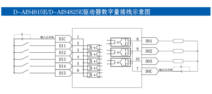
د – AIS4815E/د – AIS4825E مخطط تخطيطي للأسلاك الرقمية للسائق
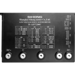
د – AIS4815E/د – وصف منفذ أسلاك برنامج التشغيل AIS4825E
CN1: واجهة خط إمدادات الطاقة ومرحلة المحرك
| رقم التعريف الشخصي | رمز | وظيفة |
| 1 | + | مدخلات الطاقة إيجابية |
| 2 | – | مدخلات الطاقة سلبية |
| 3 | دبليو | المحرك دبليو – مرحلة |
| 4 | V | المحرك الخامس – مرحلة |
| 5 | ش | موتور يو – مرحلة |
CN2: واجهة تشفير المحرك
| رقم التعريف الشخصي | رمز | وظيفة |
| 1 | +5V | 5إخراج الخامس |
| 2 | 0V | 0إخراج الخامس |
| 3 | نورث كارولاينا | محجوز |
| 4 | نورث كارولاينا | محجوز |
| 5 | اس دي+ | نقل البيانات |
| 6 | SD- | استقبال البيانات |
| 7 | بي | أرضي |
CN4: واجهة فرامل المحرك
| رقم التعريف الشخصي | رمز | وظيفة |
| 1 | برك + | مخرج الفرامل + |
| 2 | برك- | مخرج الفرامل – |
CN3: واجهة إدخال وإخراج الإشارة الرقمية
| رقم التعريف الشخصي | رمز | وظيفة |
| 1 | ديكوم | محطة الإدخال المشتركة |
| 2 | دي12 | إعادة ضبط التنبيه |
| 3 | دي13 | توقف الطوارئ |
| 4 | دي14 | هرولة – إيجابي |
| 5 | دي15 | هرولة – يعكس |
| 6 | دوكوم | محطة الإخراج المشتركة |
| 7 | افعل1 | سيرفو جاهز |
| 8 | DO2 | إنذار خطأ |
| 9 | DO3 | الانتهاء من تحديد المواقع |
CN7/CN8: واجهة اتصالات الحافلة
| رقم التعريف الشخصي | إيثركات |
| 1 | تد+ |
| 2 | TD- |
| 3 | آر دي+ |
| 4 | \ |
| 5 | \ |
| 6 | أردي- |
| 7 | \ |
| 8 | \ |
CN9: واجهة تفريغ الكبح
| رقم التعريف الشخصي | رمز | وظيفة |
| 1 | ف+ | حافلة العاصمة + |
| 2 | د- | تحرير الكبح |
CN10: 485 واجهة الاتصالات
| رقم التعريف الشخصي | 485 واجهة |
| 1 | 485أ |
| 2 | 485ب |
| 3 | أرض |
| 4 | 485ب |
| 5 | نورث كارولاينا |
| 6 | نورث كارولاينا |
| 7 | نورث كارولاينا |
| 8 | نورث كارولاينا |
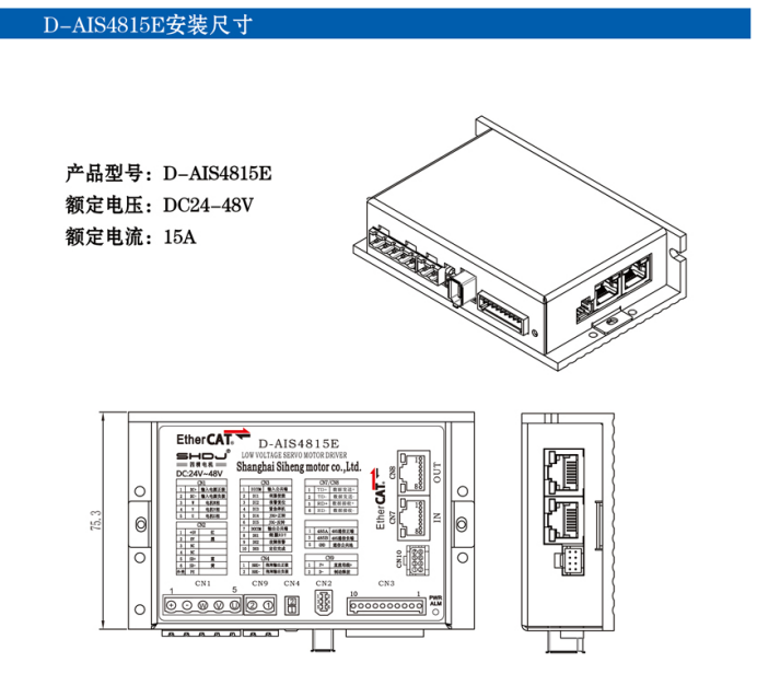
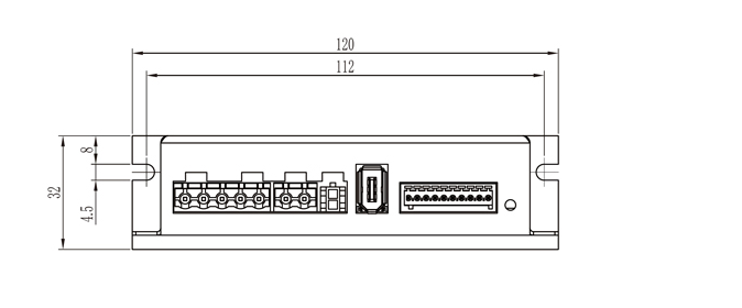
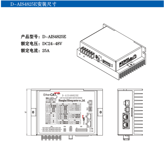
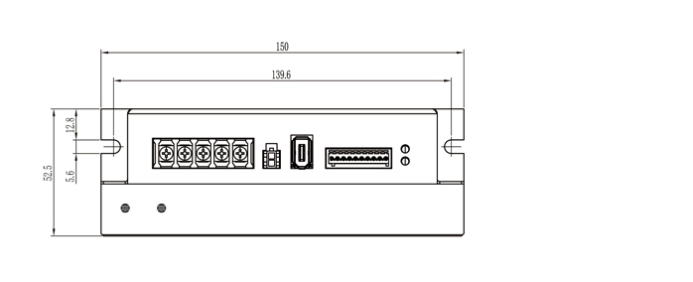
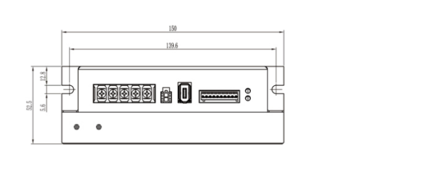
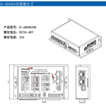
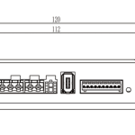
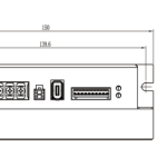
د – أبعاد التثبيت AIS4815E
نموذج المنتج: د – AIS4815E
الجهد المقنن: DC24 – 48V
التصنيف الحالي: 15أ