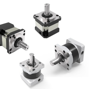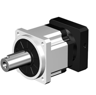

IB/IBR Reducer
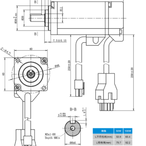
The output planetary carrier of the reducer adopts an integrated nut to eliminate axial clearance design. The front and rear bearings are distributed in a large span within the integral box body, forming a super-strong integrated structure to ensure high torsional rigidity, super-strong radial load – carrying capacity and excellent axial load – carrying capacity. The one – time processing and completion process is adopted to ensure extremely high coaxiality.
- Description
Description
IB Core Features
Comprehensive Performance Parameters of IB Reducer
| Specification | Number of Sections | Reduction Ratio | IB042 | IB060 | IB090 | IB115 | IB142 | IB180 | IB220 |
|---|---|---|---|---|---|---|---|---|---|
| 3 | 13 | 35 | 100 | 190 | 440 | 743 | 2042 | ||
| 4 | 18 | 50 | 120 | 250 | 770 | 1780 | 2967 | ||
| 5 | 17 | 45 | 115 | 245 | 635 | 1152.5 | 2062 | ||
| 6 | 12 | 40 | 105 | 240 | 500 | 820 | 1760 | ||
| 8 | 12 | 38 | 95 | 210 | 450 | 800 | 1350 | ||
| 10 | 12 | 32 | 86 | 196 | 400 | 710 | 1300 | ||
| Rated Torque T₂N | 1 | 9 | 13 | 35 | 100 | 190 | 440 | 743 | 2042 |
| 12 | 18 | 50 | 120 | 250 | 770 | 1780 | 2967 | ||
| 15 | 17 | 45 | 115 | 245 | 635 | 1152.5 | 2062 | ||
| 16 | 18 | 50 | 120 | 250 | 770 | 1780 | 2967 | ||
| 20 | 18 | 50 | 120 | 250 | 770 | 1780 | 2967 | ||
| 2 | 25 | 17 | 45 | 115 | 245 | 635 | 1152.5 | 2062 | |
| 30 | 17 | 45 | 115 | 245 | 635 | 1152.5 | 2062 | ||
| 32 | 18 | 50 | 120 | 250 | 770 | 1780 | 2967 | ||
| 40 | 17 | 45 | 115 | 245 | 635 | 1152.5 | 2062 | ||
| 50 | 17 | 45 | 115 | 245 | 635 | 1152.5 | 2062 | ||
| 64 | 12 | 38 | 95 | 210 | 450 | 800 | 1350 | ||
| 80 | 12 | 38 | 95 | 210 | 450 | 800 | 1350 | ||
| Maximum Acceleration Torque T₂B | 1.8*T2N (1.8 times the rated torque) | 1.8*T2N (1.8 times the rated torque) | 1.8*T2N (1.8 times the rated torque) | 1.8*T2N (1.8 times the rated torque) | 1.8*T2N (1.8 times the rated torque) | 1.8*T2N (1.8 times the rated torque) | 1.8*T2N (1.8 times the rated torque) | 1.8*T2N (1.8 times the rated torque) | |
| Emergency stop torqueT2NOT | 3*T2N (3 times the rated torque) | 3*T2N (3 times the rated torque) | 3*T2N (3 times the rated torque) | 3*T2N (3 times the rated torque) | 3*T2N (3 times the rated torque) | 3*T2N (3 times the rated torque) | 3*T2N (3 times the rated torque) | 3*T2N (3 times the rated torque) | |
| Rated Input Speed | rpm | 1&2 | 3000 | 3000 | 3000 | 3000 | 2000 | 1500 | 1000 |
| Maximum Input Speed | rpm | 1&2 | 6000 | 6000 | 6000 | 6000 | 4000 | 3000 | 2000 |
| P1 – arcmin | 1 | 10 | 6 | 6 | 6 | 6 | 6 | 10 | |
| Precision Grade | 2 | 12 | 8 | 8 | 8 | 8 | 8 | 12 | |
| P2 – arcmin | 1 | 16 | 8 | 8 | 8 | 8 | 8 | 16 | |
| 2 | 18 | 10 | 10 | 10 | 10 | 10 | 18 | ||
| Noise | dB(A) | 1&2 | 58 | 60 | 60 | 63 | 65 | 72 | 75 |
| Allowable Maximum Radial Load | N | 1&2 | 205 | 950 | 1600 | 2900 | 5700 | 8500 | 9200 |
| Allowable Maximum Axial Load | N | 1&2 | 340 | 740 | 1500 | 1950 | 3150 | 5800 | 7200 |
| Efficiency | % | 1 | ≥97% | ≥97% | ≥97% | ≥97% | ≥97% | ≥97% | ≥97% |
| 2 | ≥94% | ≥94% | ≥94% | ≥94% | ≥94% | ≥94% | ≥94% | ||
| Operating Ambient Temperature | ℃ | 1&2 | < – 15℃, >40℃> | < – 15℃, >40℃> | < – 15℃, >40℃> | < – 15℃, >40℃> | < – 15℃, >40℃> | < – 15℃, >40℃> | < – 15℃, >40℃> |
| Service Life | h | 1&2 | ≥20000 | ≥20000 | ≥20000 | ≥20000 | ≥20000 | ≥20000 | ≥20000 |
| Lubrication | 1&2 | Synthetic grease (free maintenance) | Synthetic grease (free maintenance) | Synthetic grease (free maintenance) | Synthetic grease (free maintenance) | Synthetic grease (free maintenance) | Synthetic grease (free maintenance) |
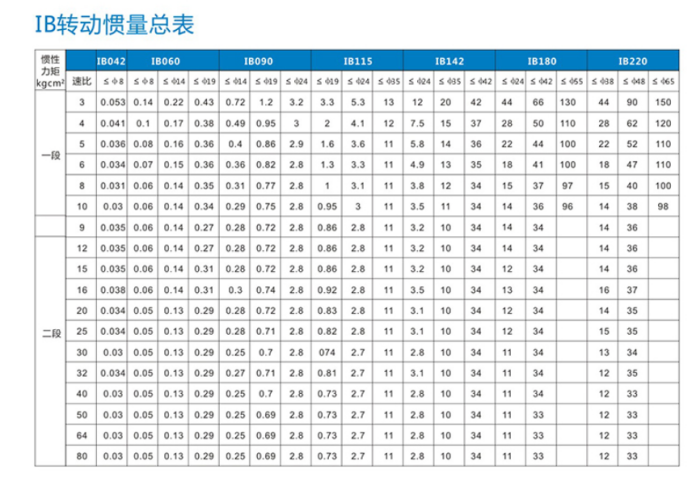
Summary Table of IB Moment of Inertia
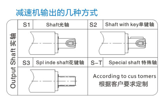
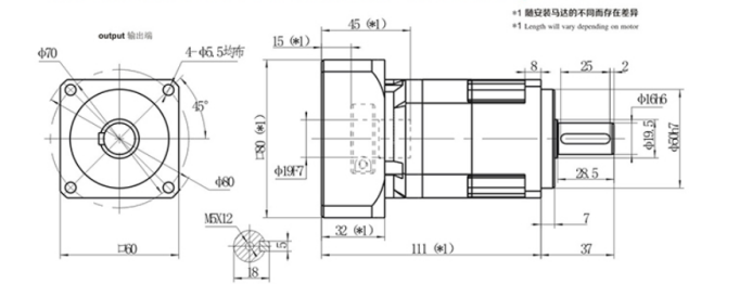
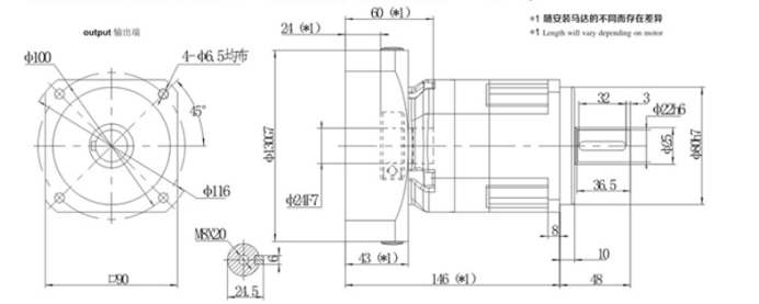
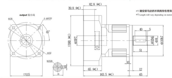
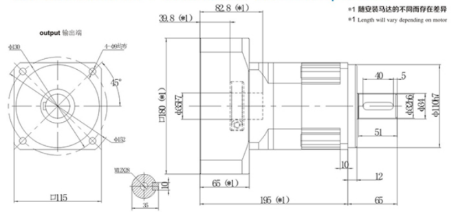
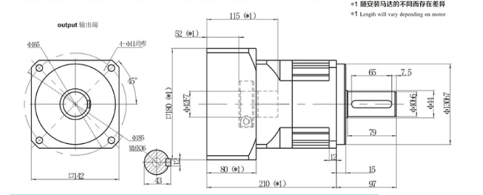
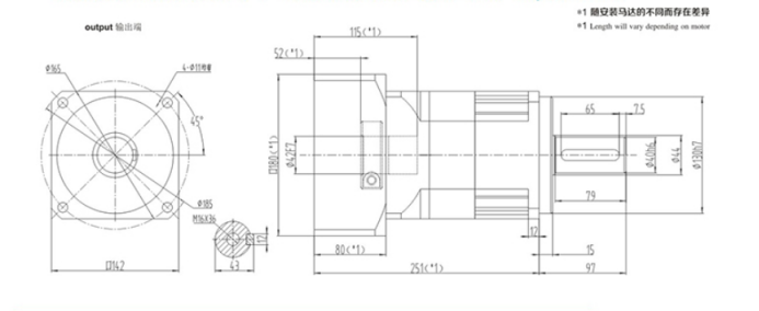
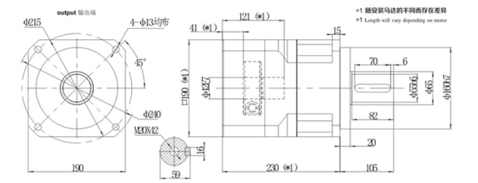
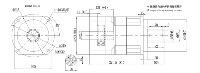
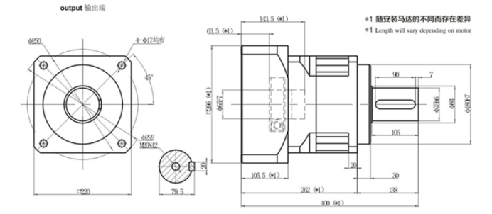
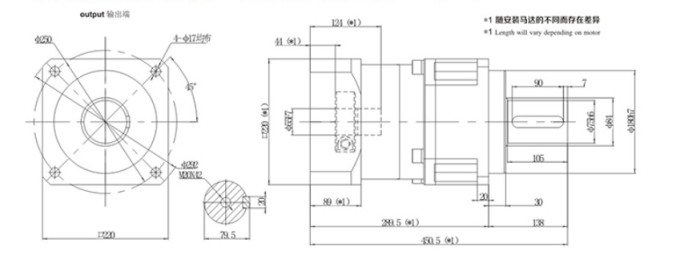
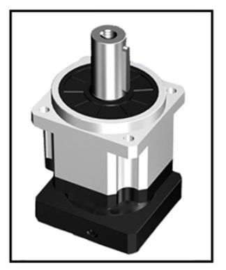
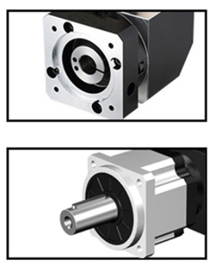
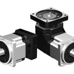
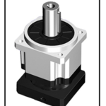
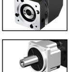
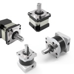
Several Output Modes of Reducer