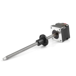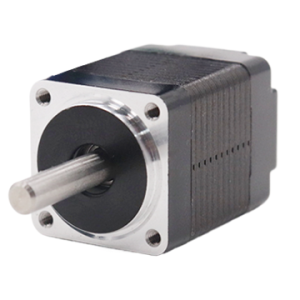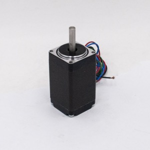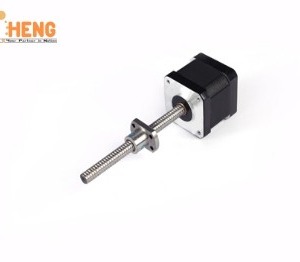
D – AIS72200A Rendah – voltan Pemandu Motor Servo Pintar
$0.00
Parameter Teknikal
- Penerangan
Penerangan
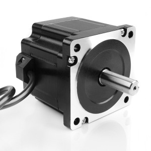
D – AIS72200A Rendah – voltan Pemandu Motor Servo Pintar
Butiran Produk
Ia mempunyai kestabilan yang kuat, tinggi – kedudukan ketepatan, tindak balas motor yang tinggi, bunyi rendah, penjanaan haba rendah, baiklah – reka bentuk berstruktur, kapasiti beban lampau yang kuat, fungsi praktikal dan kaya, dan aplikasi yang ringkas dan mudah. Ia mempunyai perlindungan terhadap over – voltan, bawah – voltan, terlebih laju, habis – semasa, terlebih beban, keabnormalan pengekod, sisihan kedudukan, gerai, keabnormalan parameter, dll.
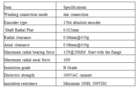
Spesifikasi Teknikal
| Model Pemacu | Julat Voltan (V) | Arus dinilai (A) |
| D – AIS24008A | 24 – 36 | 8 |
| D – AIS48015A | 24 – 48 | 15 |
| D – AIS48025A | 24 – 60 | 25 |
| D – AIS48050A | 24 – 72 | 50 |
| D – AIS48100A | 36 – 72 | 100 |
| D – AIS72200A | 48 – 96 | 200 |
| D – AIS72300A | 48 – 96 | 300 |
| Kaedah Kawalan | ① Kawalan Kedudukan ② Kawalan Kelajuan ③ Kawalan Tork ④ Kawalan Komunikasi |
| Ciri-ciri Kawalan | Respons Kekerapan Kelajuan: ≥200Hz, Frekuensi Nadi Diterima ≤200kHz, Kadar Turun Kelajuan: < ±0.03 (Muatkan 0 – 100%): < ±0.02×(0.9 – 1.1) Voltan Bekalan Kuasa |
| Fungsi Pemantauan | Kelajuan Semasa, Input DI, DO Output, Kedudukan Semasa, Pengumpulan Nadi Input Perintah, Kadar Muatan Purata, Kiraan Sisihan Kedudukan, Arus Fasa Motor, Nilai Voltan Bas, Suhu Modul, Rekod Penggera, Kelajuan Sepadan dengan Frekuensi Nadi Perintah, Status Operasi, dll. |
| Rumah – Fungsi kembali | 13 Macam Autonomous (Cari) Rumah – kembali Mod, dan Rumah – Fungsi Offset titik |
| Fungsi Rs485 | Ikut Modbus Standard – Protokol Rtu, satu – kepada – Dua Dua – Cara Antara Muka Komunikasi untuk Rangkaian Mudah dan Sambungan Selari |
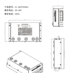
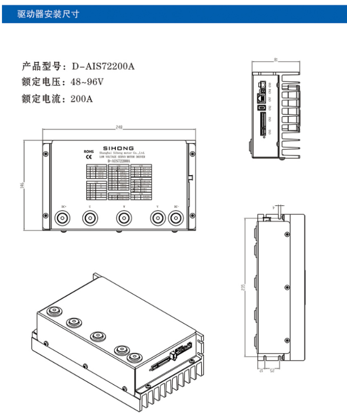
Dimensi Pemasangan Pemandu
Model Produk: D – AIS72200A
Voltan dinilai: 48 – 96V
Arus dinilai: 200A
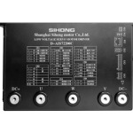
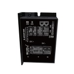
Berpisah – taip Antara Muka Perkakasan Pemacu
Model pemacu yang berkenaan: D – AISXX005A / D – AISXX0015A / D – AISXX0025A / D – AISXX0040A / D – AISXX00100A / D – AISXX00200A
Berpisah – taip Gambarajah Antaramuka Pemacu AI MOTOR
| Nombor Siri | Simbol | Fungsi | Teguran | |
| Cn1 | 1 | U | Motor U – fasa | Kabel kuasa antara muka JVW untuk menyesuaikan motor |
| 2 | V | Enjin V – fasa | ||
| 3 | W | Motor W – fasa | ||
| 4 | DC – | Kutub negatif bekalan kuasa input | Bekalan kuasa DC input luaran mesti membezakan kutub positif dan negatif; julat voltan: DC48V | |
| 5 | DC+ | Kutub positif bekalan kuasa input | ||
| Cn2 | 1 | 5V+ | Antara muka kuasa pengekod motor | Antara muka kuasa untuk menyesuaikan pengekod motor |
| 2 | Gnd | Antara muka kuasa | ||
| 3 | NC | Terminal kosong | Tiada fungsi | |
| 4 | NC | Terminal kosong | Tiada fungsi | |
| 5 | SD+ | Antara muka komunikasi pengekod motor | Antara muka komunikasi untuk menyesuaikan pengekod motor | |
| 6 | SD – | |||
| Cn3 | 1 | DARI – COM | Terminal biasa isyarat input | Terminal biasa untuk semua isyarat DI input. Apabila DI – COM disambungkan ke kutub positif, kawalan negatif DI adalah berkesan; apabila MASUK – COM disambungkan ke kutub negatif, kawalan positif DI adalah berkesan |
| 2 | DI1 | Terminal isyarat input 1 | Kilang – fungsi yang ditetapkan lalai: Dayakan servo | |
| 3 | DI2 | Terminal isyarat input 2 | Kilang – fungsi yang ditetapkan lalai: Tetapan semula penggera | |
| 4 | DI3 | Terminal isyarat input 3 | Kilang – fungsi yang ditetapkan lalai: Perhentian kecemasan | |
| 5 | DI4 | Terminal isyarat input 4 | Kilang – fungsi yang ditetapkan lalai: JOG joging positif | |
| 6 | DI5 | Terminal isyarat input 5 | Kilang – fungsi yang ditetapkan lalai: JOG jog negatif | |
| 7 | LAKUKAN – COM | Terminal biasa isyarat keluaran | Terminal biasa untuk semua isyarat DO keluaran. Apabila DO – COM disambungkan ke kutub positif, output positif tindakan DO adalah berkesan; apabila LAKUKAN – COM disambungkan ke kutub negatif, keluaran negatif tindakan DO adalah berkesan | |
| 8 | DO1 | Terminal isyarat keluaran 1 | Kilang – fungsi yang ditetapkan lalai: Servo sedia | |
| 9 | DO2 | Terminal isyarat keluaran 2 | Kilang – fungsi yang ditetapkan lalai: Output penggera kerosakan | |
| 10 | DO3 | Terminal isyarat keluaran 3 | Kilang – fungsi yang ditetapkan lalai: Output penyiapan kedudukan | |
| Cn4 | 1 | BRK+ | Kutub positif keluaran brek | Antara muka untuk menyesuaikan brek mekanikal (brek) daripada motor itu |
| 2 | BRK – | Kutub negatif keluaran brek |
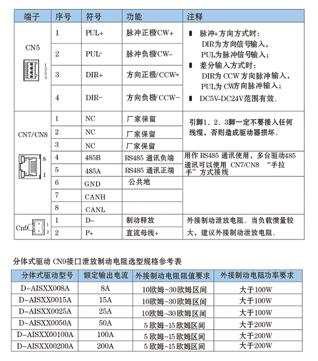
| Terminal | Nombor Siri | Simbol | Fungsi | Teguran |
| CN5 | 1 | PUL+ | Kutub nadi positif (CW+) | Apabila dalam nadi + mod arah: DIR ialah input isyarat arah, dan PUL ialah input isyarat nadi; apabila dalam mod input pembezaan: DIR ialah input nadi arah CCW, dan PUL ialah input nadi arah CW; berkesan dalam DC5V – Julat DC24V |
| 2 | PUL – | Kutub nadi negatif (CW – ) | ||
| 3 | Dir+ | Kutub arah positif (CCW+) | ||
| 4 | Dir – | Kutub arah negatif (CCW – ) | ||
| CN7/CN8 | 1 | NC | Dipelihara oleh pengilang | Pin 1, 2, dan 3 tidak boleh disambungkan ke mana-mana wayar, jika tidak pemandu akan rosak |
| 2 | NC | Dipelihara oleh pengilang | ||
| 3 | NC | Dipelihara oleh pengilang | ||
| 4 | 485B | Terminal negatif komunikasi RS485 | Digunakan untuk komunikasi RS485. Pemacu berbilang boleh disambungkan dalam a “daisy – rantai” menggunakan CN7/CN8 untuk komunikasi RS485 | |
| 5 | 485A | Terminal positif komunikasi RS485 | ||
| 6 | Gnd | Persamaan | ||
| 7 | Sup | |||
| 8 | Hidup | |||
| Cn9 | 1 | D – | Pelepasan brek | Sambungkan perintang pelepasan brek luaran. Apabila inersia beban besar, adalah disyorkan untuk menyambung perintang pelepasan brek luaran |
| 2 | P+ | bas DC + |
Jadual Rujukan Spesifikasi Pemilihan untuk Menyahcas Perintang Brek Split – taip Antara Muka Drive Cn9
| Berpisah – taip Model Pemacu | Arus Keluaran Dinilai | Keperluan Nilai Rintangan Perintang Brek Luaran | Keperluan Kuasa Perintang Brek Luaran |
| D – AISXX008A | 8A | 10 ohm – 30 julat ohm | Lebih daripada 100W |
| D – AISXX0015A | 15A | 10 ohm – 30 julat ohm | Lebih daripada 100W |
| D – AISXX0025A | 25A | 10 ohm – 30 julat ohm | Lebih daripada 100W |
| D – AISXX0050A | 50A | 5 ohm – 15 julat ohm | Lebih daripada 200W |
| D – AISXX00100A | 100A | 5 ohm – 15 julat ohm | Lebih daripada 200W |
| D – AISXX00200A | 200A | 5 ohm – 15 julat ohm | Lebih daripada 200W |
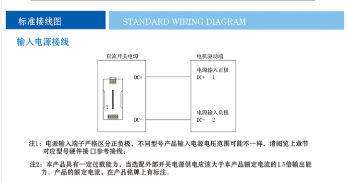
Rajah Pendawaian Standard
Pendawaian Bekalan Kuasa Input
Nota 1: Terminal bekalan kuasa input mesti membezakan kutub positif dan negatif dengan tegas. Julat voltan bekalan kuasa input mungkin berbeza untuk model yang berbeza. Sila rujuk pendawaian rujukan antara muka perkakasan untuk model yang sepadan dalam bab sebelumnya.
Nota 2: Produk ini mempunyai kapasiti beban lampau tertentu. Apabila memilih bekalan kuasa pensuisan luaran, kapasiti keluaran sepatutnya 1.5 kali nilai arus produk ini. Arus undian produk ditunjukkan pada papan nama.
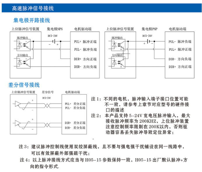
tinggi – Pendawaian Isyarat Nadi laju
Pengumpul – Pendawaian Terbuka
Pendawaian Isyarat Berbeza
Nota 1: Untuk motor yang berbeza, kedudukan antara muka terminal input nadi mungkin berbeza-beza. Sila rujuk perihalan antara muka perkakasan model yang sepadan dalam bab sebelumnya.
Nota 2: Produk ini menyokong input nadi dengan julat voltan yang luas 5 – 24V, dan frekuensi nadi maksimum yang diterima ialah 200KHZ. Bahagian atas – peranti nadi aras perlu memberi perhatian kepada mengehadkan kekerapan kepada dalam 200K untuk mengelakkan pemandu daripada mudah kehilangan nadi dan menyebabkan keabnormalan kedudukan.
Nota 3: Adalah disyorkan untuk menggunakan dua kali ganda – wayar terlindung untuk talian kawalan nadi dan elakkan meletakkannya dalam litar yang sama dengan kuat – sumber gangguan semasa, yang berkesan boleh melindungi gangguan magnet luar yang kuat.
Nota 4: Kaedah sambungan nadi di atas harus konsisten dengan H05 – 15 parameter. Lalai kilang untuk H05 – 15 ialah nadi + mod arahan arah.
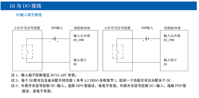
Pendawaian DI dan DO
Pendawaian Terminal Input AT
Nota 1: Voltan kawalan terminal input adalah sah pada DC12 – 24V.
Nota 2: Setiap DI boleh diberikan fungsi yang berbeza secara bebas (merujuk kepada 4.2 Bahagian parameter DIDO), tetapi fungsi yang sama tidak boleh diberikan kepada berbilang DI.
Nota 3: Untuk kawalan isyarat suis luaran dengan DC – input, pilih NPN – kaedah sambungan jenis, di mana rendah – tahap adalah berkesan; untuk kawalan isyarat suis luaran dengan input DC+, pilih PNP – kaedah sambungan jenis, mana tinggi – tahap adalah berkesan.
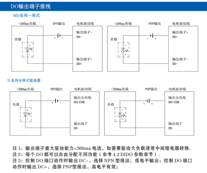
Pendawaian Terminal Keluaran DO
Nota 1: Kapasiti pemanduan maksimum terminal keluaran ialah <300ma semasa. Jika beban yang besar perlu dipandu, geganti harus digunakan untuk penukaran.
Nota 2: Setiap DO boleh diberikan fungsi yang berbeza secara bebas (merujuk kepada 4.2 Bahagian parameter DIDO).
Nota 3: Apabila mengawal tindakan port DO, jika DC – adalah keluaran, pilih NPN – kaedah sambungan jenis, di mana rendah – tahap output adalah berkesan; jika DC+ adalah output, pilih PNP – kaedah sambungan jenis, mana tinggi – tahap output adalah berkesan.
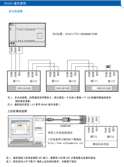
Pendawaian Komunikasi RS485
Berbilang – Sambungan Hamba
Nota 1: Untuk berbilang – sambungan hamba, jika bunyi isyarat komunikasi adalah besar, adalah disyorkan untuk menambah a 120 – perintang terminal ohm kepada hamba terakhir untuk memastikan kualiti komunikasi.
Nota 2: Untuk komunikasi – kandungan berkaitan, merujuk kepada (bahagian 4.5 RS485 – parameter berkaitan).
Sambungan Penyahpepijatan Komputer Hos
Nota 1: Biasanya, komputer tidak mempunyai langsung 485 antara muka, dan USB – kepada – 485 penukar diperlukan untuk menyambung kepada pemacu motor hamba.
Nota 2: Perisian penyahpepijatan komputer hos untuk PC boleh dimuat turun dari tapak web rasmi syarikat kami, yang memudahkan pengguna untuk menyahpepijat.