
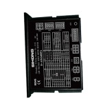

D – AIS24008A Low – voltage Intelligent Servo Motor Driver
$0.00
Technical Parameters
- Description
Description
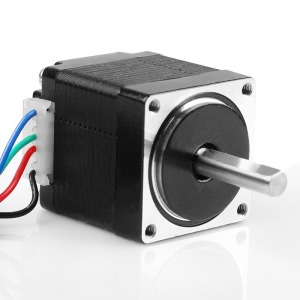
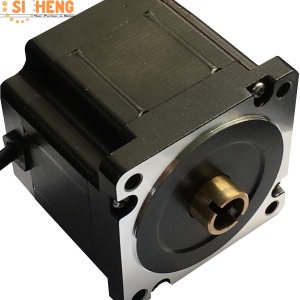
D – AIS24008A Low – voltage Intelligent Servo Motor Driver
Product Details
It features strong stability, high – precision positioning, high motor response, low noise, low heat generation, fine – structured design, strong overload capacity, practical and rich functions, and simple and convenient application. It has protections against over – voltage, under – voltage, overspeed, over – current, overload, encoder abnormalities, position deviation, stall, parameter abnormalities, etc.
Technical Specifications
| Drive Model | Voltage Range (V) | Rated Current (A) |
| D – AIS24008A | 24 – 36 | 8 |
| D – AIS48015A | 24 – 48 | 15 |
| D – AIS48025A | 24 – 60 | 25 |
| D – AIS48050A | 24 – 72 | 50 |
| D – AIS48100A | 36 – 72 | 100 |
| D – AIS72200A | 48 – 96 | 200 |
| D – AIS72300A | 48 – 96 | 300 |
| Control Method | ① Position Control ② Speed Control ③ Torque Control ④ Communication Control |
| Control Characteristics | Speed Frequency Response: ≥200Hz, Received Pulse Frequency ≤200kHz, Speed Fluctuation Rate: < ±0.03 (Load 0 – 100%): < ±0.02×(0.9 – 1.1) Power Supply Voltage |
| Monitoring Function | Current Speed, DI Input, DO Output, Current Position, Command Input Pulse Accumulation, Average Load Rate, Position Deviation Count, Motor Phase Current, Bus Voltage Value, Module Temperature, Alarm Record, Command Pulse Frequency Corresponding Speed, Operating Status, etc. |
| Home – return Function | 13 Kinds of Autonomous (Search) Home – return Modes, and Home – point Offset Function |
| Rs485 Function | Follows Standard Modbus – Rtu Protocol, One – to – Two Two – way Communication Interface for Easy Networking and Parallel Connection |
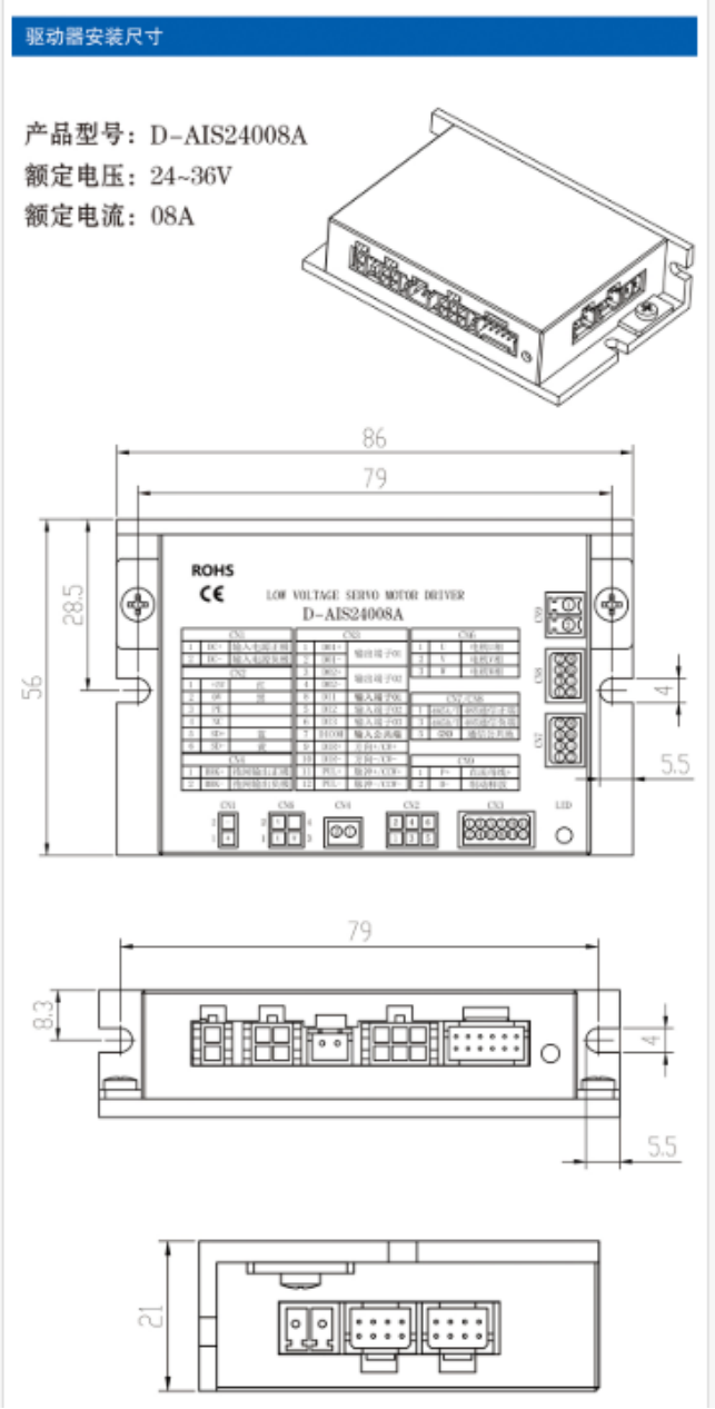
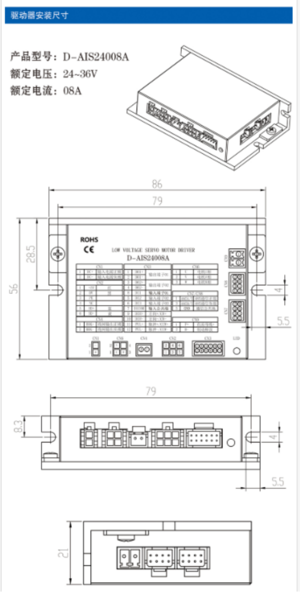
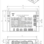
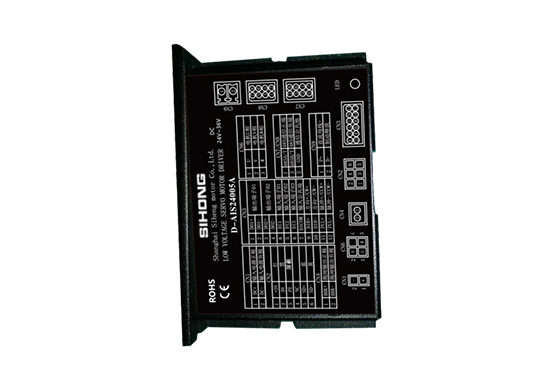
Driver Installation Dimensions
Product Model: D – AIS24008A
Rated Voltage: 24 – 36V
Rated Current: 08A
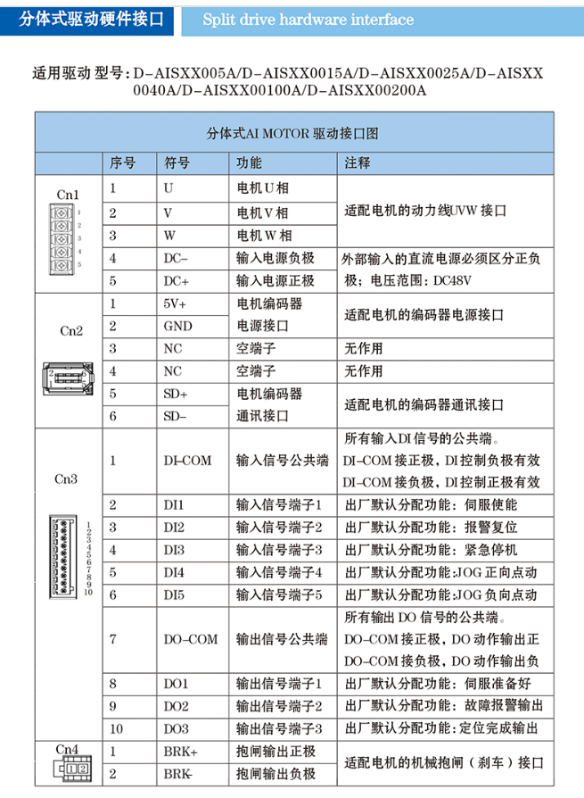
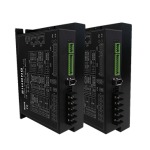
Split – type Drive Hardware Interface
Applicable drive models: D – AISXX005A / D – AISXX0015A / D – AISXX0025A / D – AISXX0040A / D – AISXX00100A / D – AISXX00200A
Split – type AI MOTOR Drive Interface Diagram
| Serial Number | Symbol | Function | Remarks | |
| Cn1 | 1 | U | Motor U – phase | Power cable JVW interface for adapting the motor |
| 2 | V | Motor V – phase | ||
| 3 | W | Motor W – phase | ||
| 4 | DC – | Negative pole of input power supply | The external input DC power supply must distinguish positive and negative poles; voltage range: DC48V | |
| 5 | DC+ | Positive pole of input power supply | ||
| Cn2 | 1 | 5V+ | Motor encoder power interface | Power interface for adapting the motor encoder |
| 2 | GND | Power interface | ||
| 3 | NC | Empty terminal | No function | |
| 4 | NC | Empty terminal | No function | |
| 5 | SD+ | Motor encoder communication interface | Communication interface for adapting the motor encoder | |
| 6 | SD – | |||
| Cn3 | 1 | DI – COM | Common terminal of input signals | Common terminal for all input DI signals. When DI – COM is connected to the positive pole, the negative control of DI is effective; when DI – COM is connected to the negative pole, the positive control of DI is effective |
| 2 | DI1 | Input signal terminal 1 | Factory – default assigned function: Servo enable | |
| 3 | DI2 | Input signal terminal 2 | Factory – default assigned function: Alarm reset | |
| 4 | DI3 | Input signal terminal 3 | Factory – default assigned function: Emergency stop | |
| 5 | DI4 | Input signal terminal 4 | Factory – default assigned function: JOG positive jog | |
| 6 | DI5 | Input signal terminal 5 | Factory – default assigned function: JOG negative jog | |
| 7 | DO – COM | Common terminal of output signals | Common terminal for all output DO signals. When DO – COM is connected to the positive pole, the positive output of DO action is effective; when DO – COM is connected to the negative pole, the negative output of DO action is effective | |
| 8 | DO1 | Output signal terminal 1 | Factory – default assigned function: Servo ready | |
| 9 | DO2 | Output signal terminal 2 | Factory – default assigned function: Fault alarm output | |
| 10 | DO3 | Output signal terminal 3 | Factory – default assigned function: Positioning completion output | |
| Cn4 | 1 | BRK+ | Positive pole of brake output | Interface for adapting the mechanical brake (brake) of the motor |
| 2 | BRK – | Negative pole of brake output |
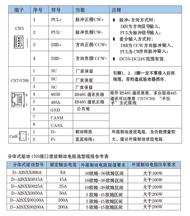
| Terminal | Serial Number | Symbol | Function | Remarks |
| CN5 | 1 | PUL+ | Positive pole of pulse (CW+) | When in pulse + direction mode: DIR is the direction signal input, and PUL is the pulse signal input; when in differential input mode: DIR is the CCW direction pulse input, and PUL is the CW direction pulse input; effective within the DC5V – DC24V range |
| 2 | PUL – | Negative pole of pulse (CW – ) | ||
| 3 | DIR+ | Positive pole of direction (CCW+) | ||
| 4 | DIR – | Negative pole of direction (CCW – ) | ||
| CN7/CN8 | 1 | NC | Reserved by the manufacturer | Pins 1, 2, and 3 must not be connected to any wires, otherwise the driver will be damaged |
| 2 | NC | Reserved by the manufacturer | ||
| 3 | NC | Reserved by the manufacturer | ||
| 4 | 485B | Negative terminal of RS485 communication | Used for RS485 communication. Multiple drives can be wired in a “daisy – chain” manner using CN7/CN8 for RS485 communication | |
| 5 | 485A | Positive terminal of RS485 communication | ||
| 6 | GND | Common ground | ||
| 7 | CANH | |||
| 8 | CANL | |||
| Cn9 | 1 | D – | Brake release | Connect an external braking discharge resistor. When the load inertia is large, it is recommended to connect an external braking discharge resistor |
| 2 | P+ | DC bus + |
Selection Specification Reference Table for Discharging Braking Resistor of Split – type Drive Cn9 Interface
| Split – type Drive Model | Rated Output Current | Requirement for Resistance Value of External Braking Resistor | Requirement for Power of External Braking Resistor |
| D – AISXX008A | 8A | 10 ohms – 30 ohms range | Greater than 100W |
| D – AISXX0015A | 15A | 10 ohms – 30 ohms range | Greater than 100W |
| D – AISXX0025A | 25A | 10 ohms – 30 ohms range | Greater than 100W |
| D – AISXX0050A | 50A | 5 ohms – 15 ohms range | Greater than 200W |
| D – AISXX00100A | 100A | 5 ohms – 15 ohms range | Greater than 200W |
| D – AISXX00200A | 200A | 5 ohms – 15 ohms range | Greater than 200W |
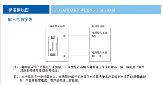
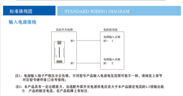
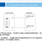
Standard Wiring Diagram
Input Power Supply Wiring
Note 1: The input power supply terminals must strictly distinguish positive and negative poles. The input power supply voltage range may vary for different models. Please refer to the hardware interface reference wiring for the corresponding model in the previous chapter.
Note 2: This product has a certain overload capacity. When selecting an external switching power supply, the output capacity should be 1.5 times the rated current of this product. The rated current of the product is indicated on the nameplate.
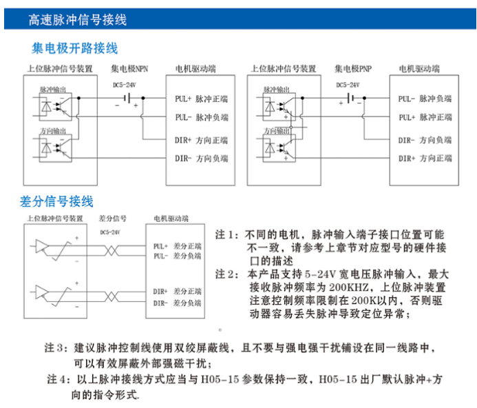
High – speed Pulse Signal Wiring
Collector – Open Wiring
Differential Signal Wiring
Note 1: For different motors, the interface positions of the pulse input terminals may vary. Please refer to the description of the hardware interface of the corresponding model in the previous chapter.
Note 2: This product supports pulse input with a wide voltage range of 5 – 24V, and the maximum received pulse frequency is 200KHZ. The upper – level pulse device should pay attention to limiting the frequency to within 200K to prevent the driver from easily losing pulses and causing positioning abnormalities.
Note 3: It is recommended to use double – shielded wires for pulse control lines and avoid laying them in the same circuit as strong – current interference sources, which can effectively shield external strong magnetic interference.
Note 4: The above pulse connection methods should be consistent with the H05 – 15 parameters. The factory default for H05 – 15 is pulse + direction command mode.
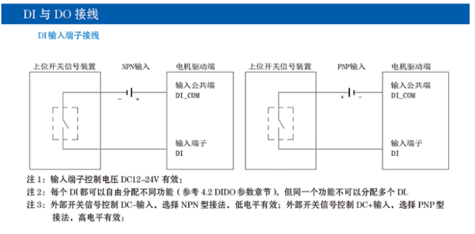
DI and DO Wiring
DI Input Terminal Wiring
Note 1: The control voltage of the input terminals is valid at DC12 – 24V.
Note 2: Each DI can be freely assigned different functions (refer to the 4.2 DIDO parameter section), but the same function cannot be assigned to multiple DIs.
Note 3: For external switch signal control with DC – input, select the NPN – type connection method, where low – level is effective; for external switch signal control with DC+ input, select the PNP – type connection method, where high – level is effective.
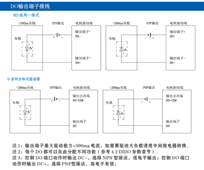
DO Output Terminal Wiring
Note 1: The maximum driving capacity of the output terminals is <300ma current. If a large load needs to be driven, a relay should be used for conversion.
Note 2: Each DO can be freely assigned different functions (refer to the 4.2 DIDO parameter section).
Note 3: When controlling the DO port action, if DC – is output, select the NPN – type connection method, where low – level output is effective; if DC+ is output, select the PNP – type connection method, where high – level output is effective.
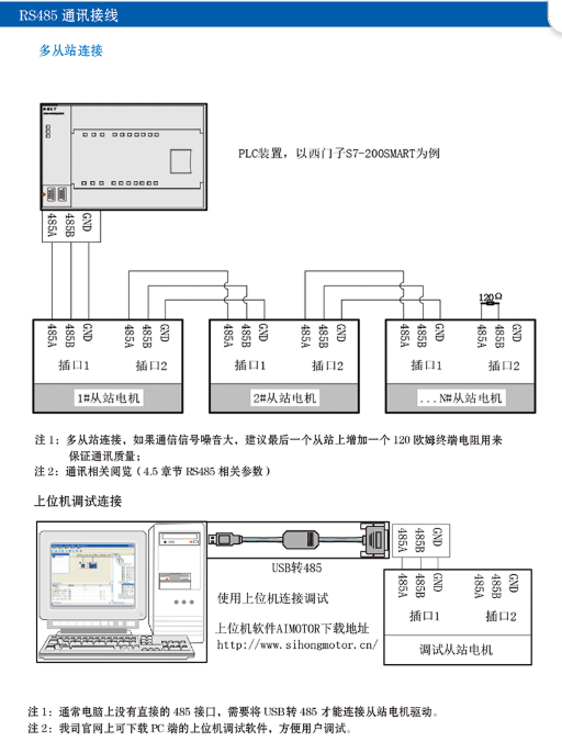
RS485 Communication Wiring
Multi – Slave Connection
Note 1: For multi – slave connection, if the communication signal noise is large, it is recommended to add a 120 – ohm terminal resistor to the last slave to ensure communication quality.
Note 2: For communication – related content, refer to (section 4.5 RS485 – related parameters).
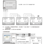
Host Computer Debugging Connection
Note 1: Usually, a computer does not have a direct 485 interface, and a USB – to – 485 converter is required to connect to the slave motor drive.
Note 2: The host computer debugging software for PC can be downloaded from our company’s official website, which is convenient for users to debug.