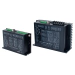
Split – type EtherCAT Bus DC Servo Driver D – AIS4815E/D – AIS4825E
$0.00
Technical Parameters
- Description
Description
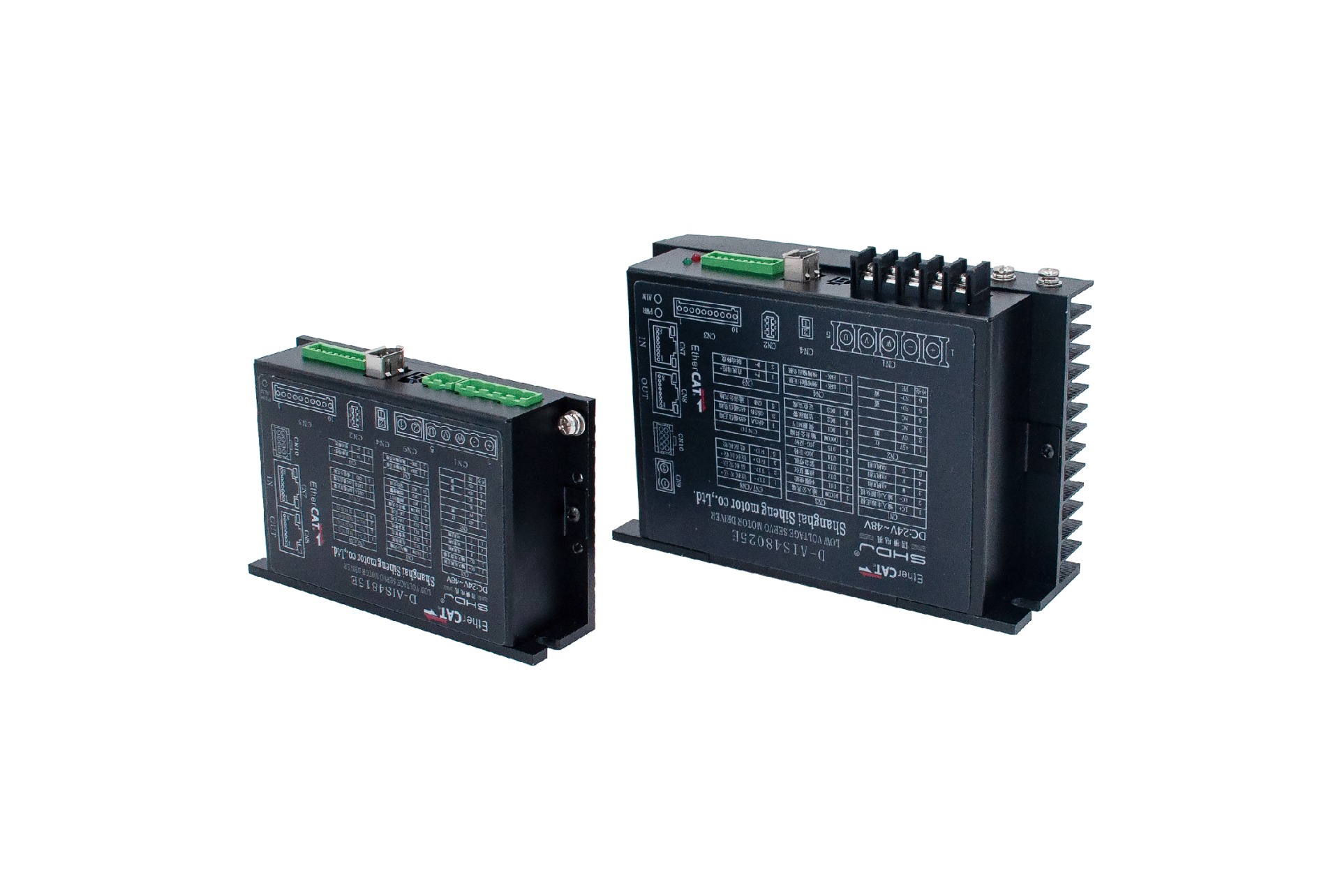
Split – type EtherCAT Bus DC Servo Driver D – AIS4815E/D – AIS4825E
Product Details
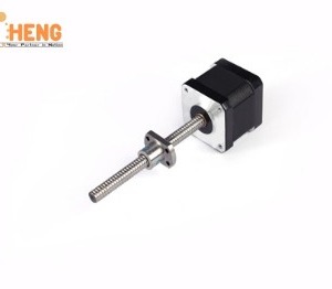
The AIMOTOR driver adopts an EtherCAT bus communication interface, integrating EtherCAT slave station technology, vector control technology, built – in ESC slave station processor, adaptive filtering technology, and closed – loop control technology. It realizes real – time control and real – time data transmission of the system, optimizing the performance of the motor. It has excellent stability and ultra – low noise; smooth and precise pure sine current vector control technology effectively reduces motor heating.
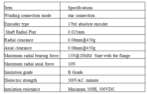
Technical Specifications
| Model Parameter | D – AIS4815E | DI – AIS4825E |
| Input Power Supply | 24VDC – 60VDC | 24VDC – 60VDC |
| Rated Current | 15A | 25A |
| Peak Current | 25A | 50A |
| Feedback Signal | 17 – bit Absolute Encoder | |
| Energy – consuming Braking | External Braking Resistor Can Be Connected | |
| Protection Function | Over – voltage Protection, Under – voltage Protection, Overload Protection, Driver Overheating Protection, etc. | |
| Cooling Method | Natural Air Cooling | |
| Digital Input | 5 – way Digital Input (Terminal Functions Can Be Set) | |
| Digital Output | 3 – way Digital Output (Terminal Functions Can Be Set) | |
| Modbus/RS485 | Maximum Supported Baud Rate | |
| EtherCAT | Supports CoE (CiA402 Protocol) and CSP/CSV/PP/PV/PT/HM Modes, Communication Speed 100M | |
| Operating Temperature | 0 – 40°C | |
| Storage Temperature | – 10°C – 70°C |
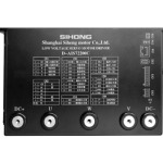
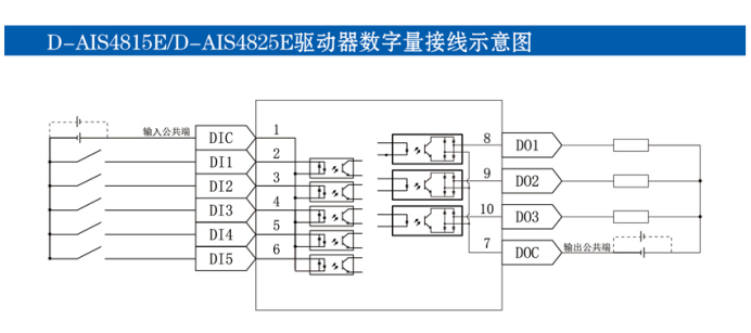
D – AIS4815E/D – AIS4825E Driver Digital Wiring Schematic Diagram
D – AIS4815E/D – AIS4825E Driver Wiring Port Description
CN1: Power Supply and Motor Phase Line Interface
| Pin Number | Symbol | Function |
| 1 | + | Input Power Positive |
| 2 | – | Input Power Negative |
| 3 | W | Motor W – phase |
| 4 | V | Motor V – phase |
| 5 | U | Motor U – phase |
CN2: Motor Encoder Interface
| Pin Number | Symbol | Function |
| 1 | +5V | 5V Output |
| 2 | 0V | 0V Output |
| 3 | NC | Reserved |
| 4 | NC | Reserved |
| 5 | SD+ | Data Transmission |
| 6 | SD- | Data Reception |
| 7 | PE | Ground |
CN4: Motor Brake Interface
| Pin Number | Symbol | Function |
| 1 | BRK+ | Brake Output + |
| 2 | BRK- | Brake Output – |
CN3: Digital Signal Input and Output Interface
| Pin Number | Symbol | Function |
| 1 | DICOM | Input Common Terminal |
| 2 | DI12 | Alarm Reset |
| 3 | DI13 | Emergency Stop |
| 4 | DI14 | JOG – Positive |
| 5 | DI15 | JOG – Reverse |
| 6 | DOCOM | Output Common Terminal |
| 7 | DO1 | Servo Ready |
| 8 | DO2 | Fault Alarm |
| 9 | DO3 | Positioning Completion |
CN7/CN8: Bus Communication Interface
| Pin Number | EtherCAT |
| 1 | TD+ |
| 2 | TD- |
| 3 | RD+ |
| 4 | \ |
| 5 | \ |
| 6 | RD- |
| 7 | \ |
| 8 | \ |
CN9: Braking Discharge Interface
| Pin Number | Symbol | Function |
| 1 | P+ | DC Bus + |
| 2 | D- | Braking Release |
CN10: 485 Communication Interface
| Pin Number | 485 Interface |
| 1 | 485A |
| 2 | 485B |
| 3 | GND |
| 4 | 485B |
| 5 | NC |
| 6 | NC |
| 7 | NC |
| 8 | NC |
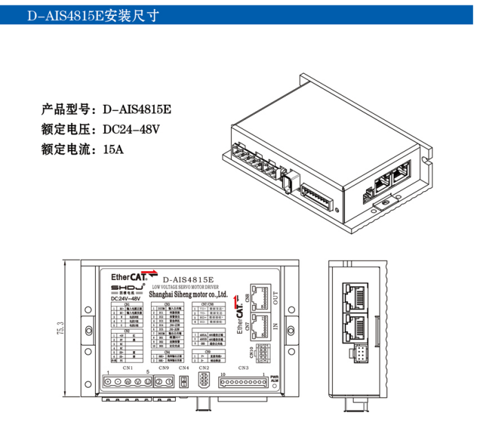
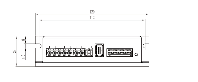
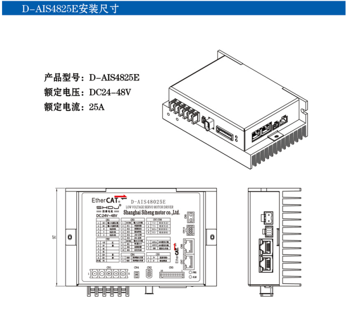
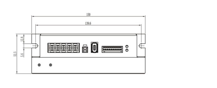
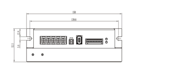
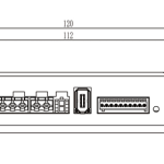
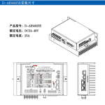
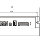
D – AIS4815E Installation Dimensions
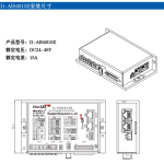
Product Model: D – AIS4815E
Rated Voltage: DC24 – 48V
Rated Current: 15A